|
|
|
Aviation Links:
|
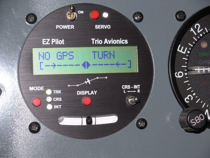
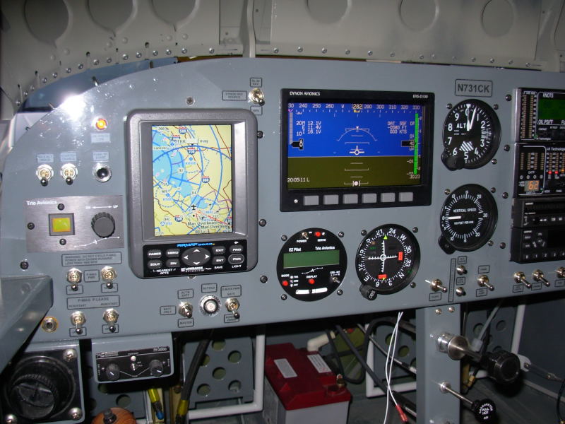
Since the roll axis autopilot was not really necessary for first flight and the Trio Avionics EZ-Pilot turn rate indication and other displays work fine without the servo connected, I concentrated on first getting the plane flying and then installed the Trio EZ-Pilot roll axis servo at about the 15 hour point in my Phase I flight test period. The picture on the left here is a close up of the control head for the Trio EZ-Pilot roll axis autopilot. The wider view of my panel on the right shows my EZ-Pilot control head installed below the Dynon EFIS, to the right of my Lowrance 2000C GPS that is coupled to the EZ-Pilot. A turn rate display can be selected on the second line of the EZ-Pilot display and that coupled with the mechanical ball lets the Trio unit serve as a slip/skid and turn rate indicator to back up same functions on the Dynon EFIS:
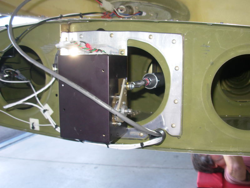
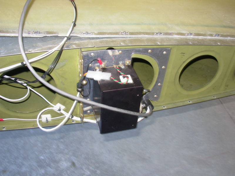
After looking at the options for installation location, I decided it would be easiest to do the wingtip installation. I had already run the shielded cable to the left wingtip before putting the wings on so the installation after I was flying really was just the mechanical installation of the servo and the pushrod that connects at the aileron bellcrank. The pictures on this page show some of my Trio EZ-Pilot servo installation details. To make the doubler on the end rib, I used some scrap 0.063 sheet left over from my first attempt at an instrument panel. The doubler is riveted to the end rib with the servo secured by #6 screws and nutplates:
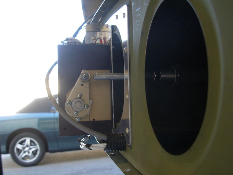
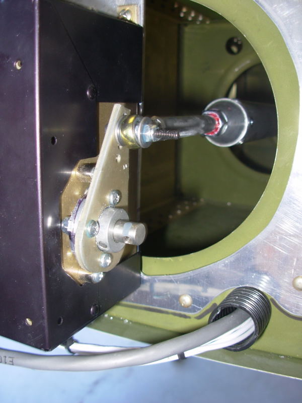
You can see from the pushrod that I used the larger diameter tubing for the relatively long pushrod length (keeps it light but enough stiffness for the length of the pushrod). I ordered an extra pushrod and threaded end fittings from Van's - same as for the fuselage to aileron bellcrank pushrod. But the large rod end bearing normally used with this pushrod doesn't work for attaching to the servo or to the bellcrank as the larger size would cause interference on both ends. To get down to the smaller rod end bearing and screws Trio intended for the connections, I used a 3/8" aluminum rod I bought at the local hardware store. I used about 3" lengths of the rod at both connections with one end of the rod drilled and tapped for the Trio supplied small rod end bearings. I cut threads on the other end to screw into the Van's supplied pushrod end fitting. Coarse threads are more common in the 3/8" size so it took a few hardware store stops to find a fine thread 3/8" die for cutting the threads, but eventually found one at Sears. I was concerned about the possibility of the pushrod rotating itself free with the extra rod getting down to the right size, so I made sure the threads are at least 75% engaged everywhere and used both jam nuts and the heavier grade loctite on the rod and bearing threads.
Here's the servo install from forward/top perspective (that's the wingtip resting on top of the wing and the wires are for the strobe/nav lights in the wingtip and the Duckworth's landing light in the outboard leading edge):
Closer look at the servo connection to the pushrod; the red loctite is visible at the jam nut on the inboard end of the smaller diameter pushrod:
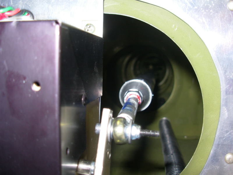
End view looking from wingtip towards the aileron bellcrank:
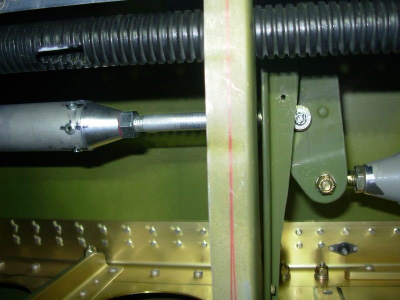
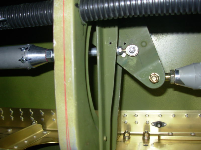
This picture was taken from underneath the left wing, looking up through the open access plate at the aileron bellcrank assembly (about mid-wing). The pushrod going to the right in this picture is the standard RV-6/6A design pushrod connection going towards the control stick. The Trio EZ-Pilot servo pushrod is the one going to the left in this picture, connecting directly to the bellcrank. The RV-6/6A bellcrank design is not nearly as easy, or "auto-pilot friendly" as some of Van's newer designs for installing a servo. This design requires careful checking of clearances and connections to prevent situations that could result in control jamming:
Same view, but with control stick in full right deflection. The small (#40) hole visible in the angle and the bellcrank was drilled per plans during construction to pin the bellcrank in the "ailerons neutral" position:
|
|
This page was last updated on 12/18/11.
Click here for questions or feedback. Copyright © 2007. All rights reserved. Chris Hand, chris@ckhand.com
|