|
|
|
Aviation Links:
|
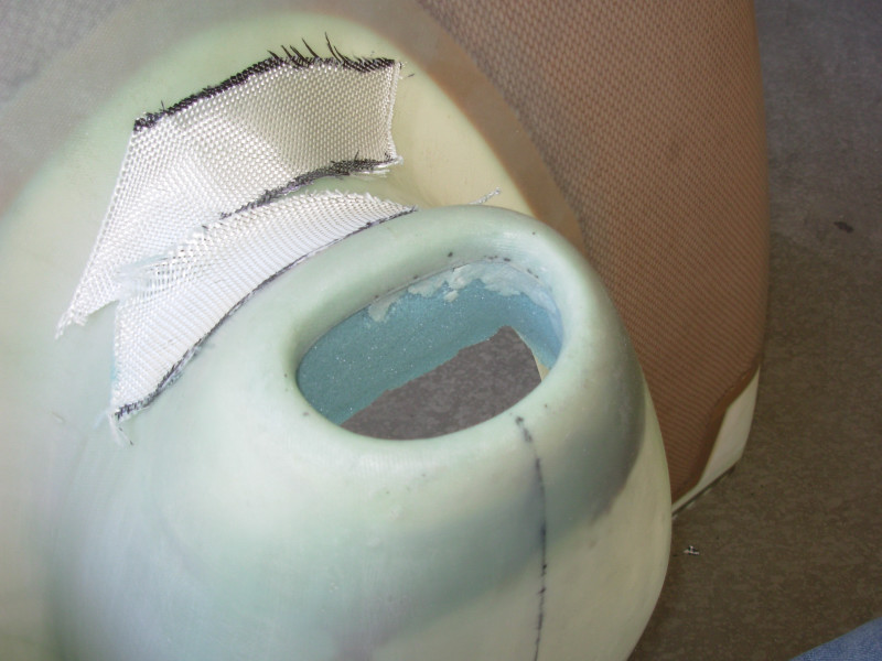
Here's the lower cowl air scoop with the foam glued in place and carved for the path to the airbox. The intent is to form a path to meet the airbox inlet and then layup a fiberglass extension of the air scoop so you end up with an air inlet with about a one quarter inch gap between the cowl air scoop and the inlet to the airbox that feeds the carb. The small gap is then bridged with the flexible air seal material riveted to the airbox shown on the previous page. Outside view of the air scoop:
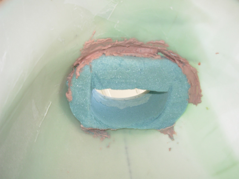
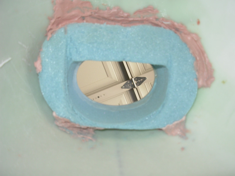
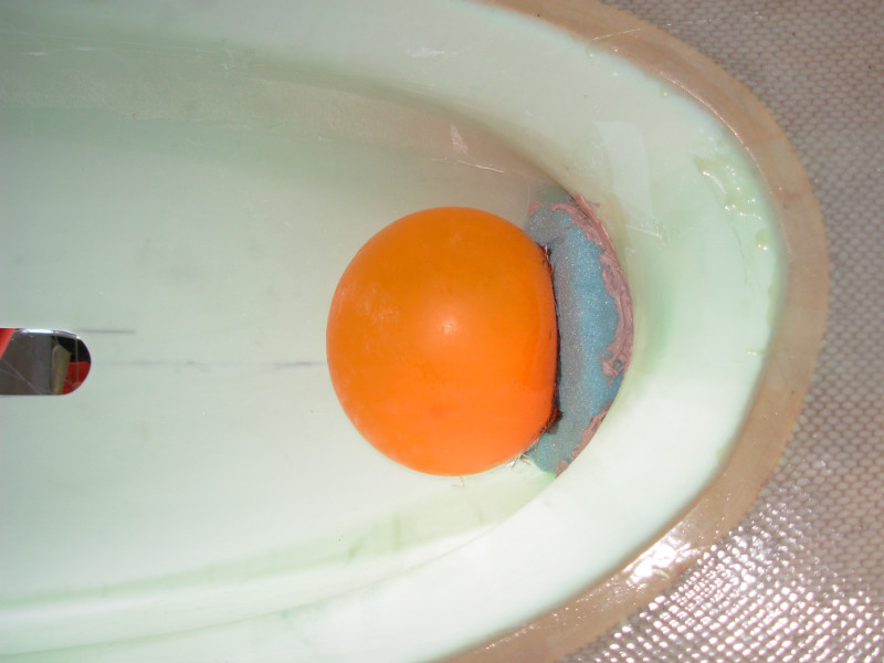
Inside view of the cowl air scoop (the blue is the foam used as fiberglass mold and the beige stuff is bondo that is temporarily holding the foam in place - all will be chipped out after the fiberglass has cured):
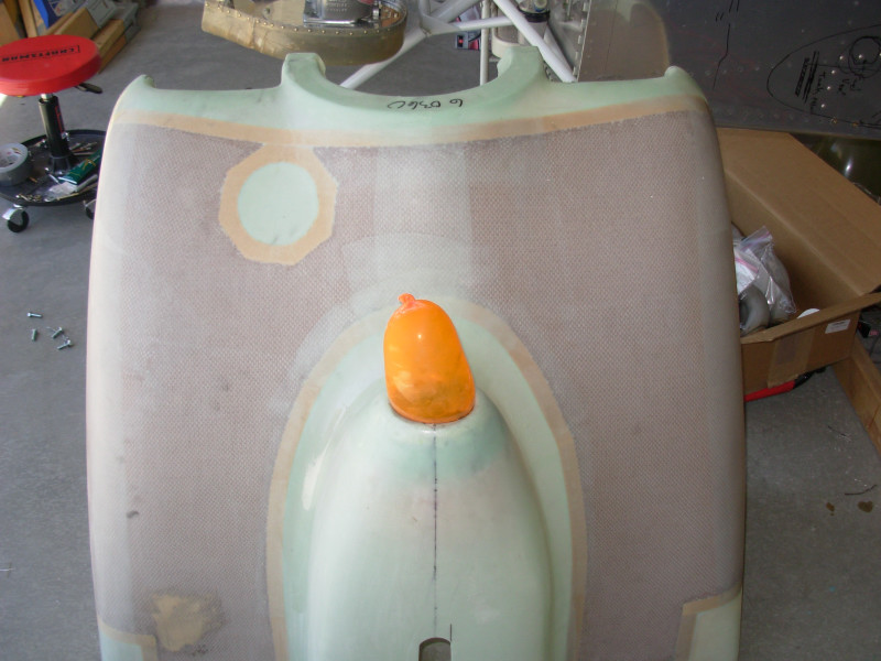
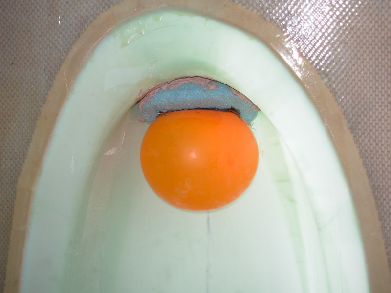
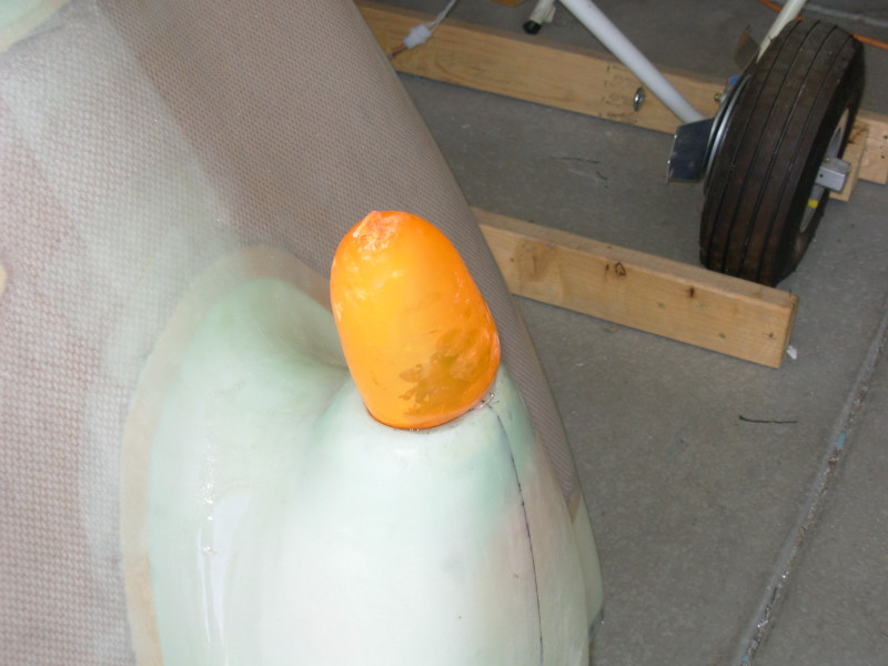
I followed the common suggestion to use a balloon to hold the wetted fiberglass in place while the resin cures. This is the outside view of the lower cowl with the balloon in the airscoop after laying up the fiberglass:
View of inside of the cowl with the balloon installed after fiberglass layup:
Another view from the outside of the cowl:
|
|
This page was last updated on 12/18/11.
Click here for questions or feedback. Copyright © 2007. All rights reserved. Chris Hand, chris@ckhand.com
|