|
|
|
Aviation Links:
|
Engine & Sys: pg 1 | pg 2 | pg 3 | pg 4 | pg 5
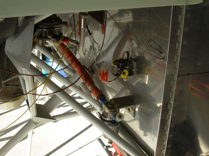
This picture is from the lower left side of the firewall, showing the fuel and oil pressure switches on the upper part of the firewall, and the fuel flow meter on the lower part of the firewall below the pressure switches. I had second thoughts on the fuel flow meter setup and later pulled it off the firewall. If I do decide to use the fuel flow sensor, I will probably come up with a solution that allows putting it between the engine driven fuel pump and the carb using flexible hoses.
A closer shot of the lower left firewall with the gascolator installed on the firewall.
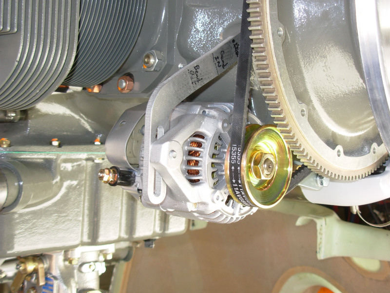
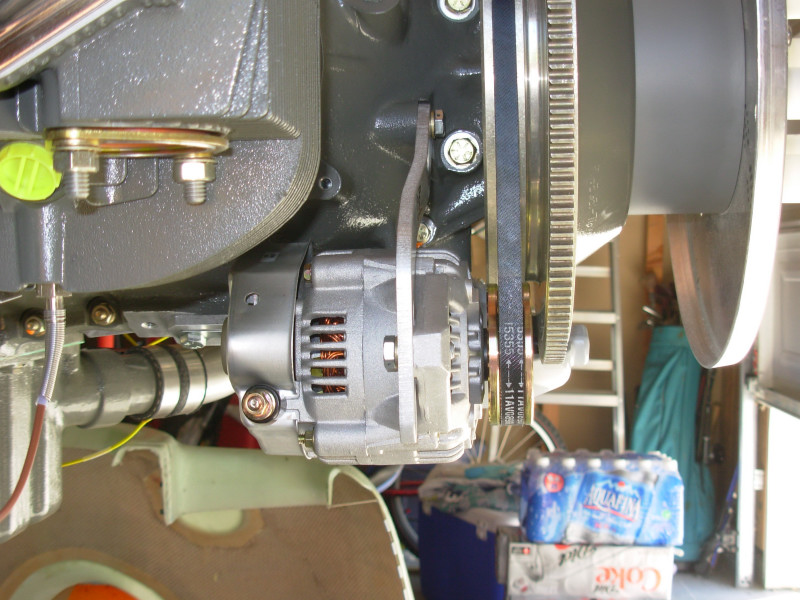
Close up of the alternator bolted in place. As you can see on the belt, the 15355 part number from the auto part store worked best for me. That's a 35.5" belt and it looks like it will give plenty of clearance from the lower cowl. The alternator is the 60A internally regulated automotive alternator out of the Van's catalog. I've heard a number of these have failed with pretty short operating times but I heard all that after I bought it...so I'm going with this one and if it dies an early death I'll consider one of the Plane Power units or something else.
Only a slight joggle required in the support arm to line everything up:
Engine & Sys: pg 1 | pg 2 | pg 3 | pg 4 | pg 5
|
|
This page was last updated on 12/18/11.
Click here for questions or feedback. Copyright © 2007. All rights reserved. Chris Hand, chris@ckhand.com
|