|
|
|
Aviation Links:
|
Engine & Sys: pg 1 | pg 2 | pg 3 | pg 4 | pg 5
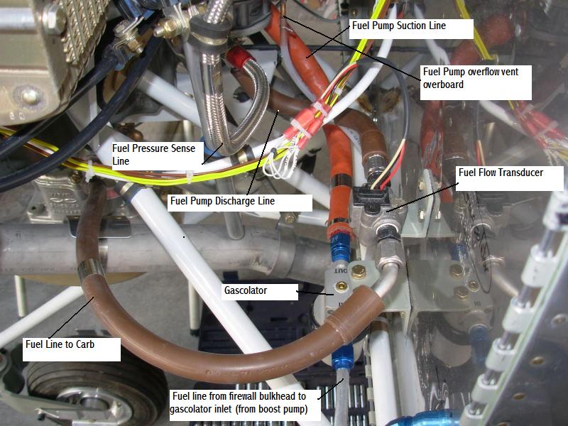
The following photos show my firewall forward fuel system configuration. Aft of the firewall, my fuel system is the standard Van's design with suction lines from each tank pickup tube going to the fuel selector valve between the seats, forward of the main spar, then the main fuel feed line goes from the selector valve to the Facet electric fuel boost pump mounted on the left fuselage side skin in the wing root area. The Facet pump discharge line goes straight forward to the firewall bulkhead fitting on the lower left side of the firewall. The firewall forward overall system flow path is illustrated in this photo with each line labeled:
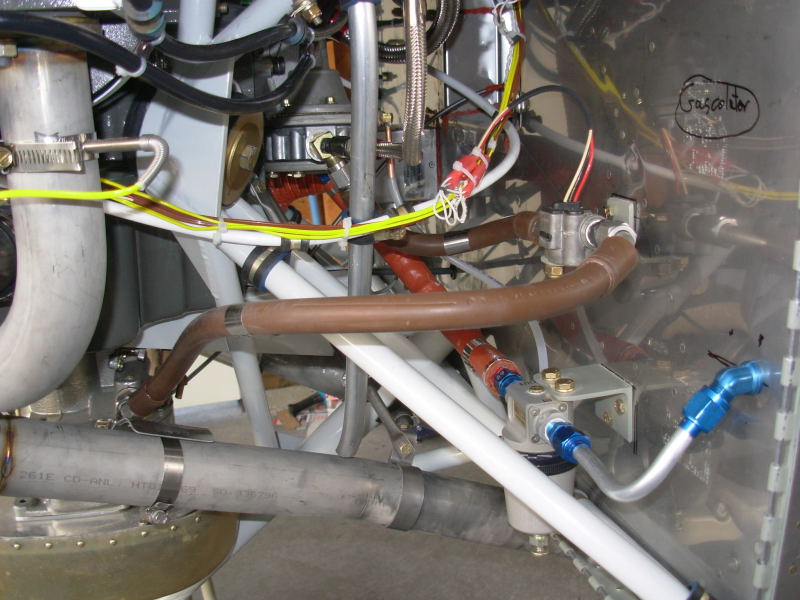
Here's the overall fwf fuel system from a slightly different vantage point (refer to picture above for which line is which):
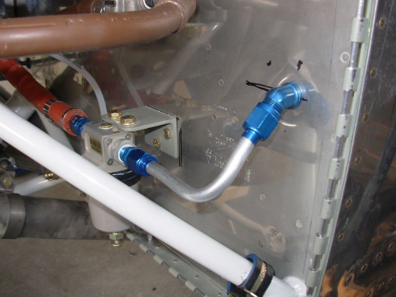
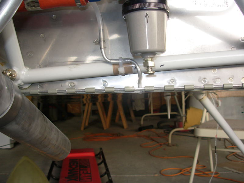
Here's a closeup of the gascolator. The fuel pump vent overboard discharge line can be seen passing through the firewall flange below and behind the gascolator:
A little wider view shows the fuel flow transducer above the gascolator. The fuel flow sensor is supposed to be placed on the discharge side of the engine driven fuel pump, although I know people have successfully installed the sensor in just about every place else in the system. You are also supposed to have 6 inches of straight line before and after the transducer but that's not really possible in an RV installation. Before the first flight, I did the recommended fuel flow testing, measured from the line that connects to the carb inlet, and I found the transducer readings to be pretty close to the actual measured flow rate with this installation. That has proven to be the case in flight testing since then when I compare the IK2000 engine monitor fuel remaining numbers with my actual fillup amounts. One side note on the hard aluminum line between the bulkhead fitting and gascolator - I did put firesleeve on that line before first flight and may eventually change it out for a flexible line (not required since both ends hard mounted on firewall).
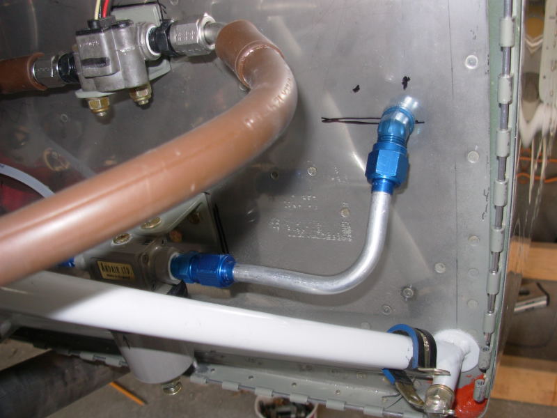
Here's a better closeup of the fuel pump vent overboard line behind the gascolator:
Engine & Sys: pg 1 | pg 2 | pg 3 | pg 4 | pg 5
|
|
This page was last updated on 12/18/11.
Click here for questions or feedback. Copyright © 2007. All rights reserved. Chris Hand, chris@ckhand.com
|