|
|
|
Aviation Links:
|
Panel: pg 1 | pg 2 | pg 3 | pg 4 | pg 5 | pg 6 Electrical: pg 1 | pg 2 | pg 3 | pg 4 | pg 5 | pg 6 | pg 7 | pg 8
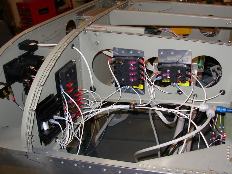
My RV-6A main electrical system architecture is shown here. It's based on the suggestions from Bob Nuckolls' book and web site, "The AeroElectric Connection". From left to right, you can see the diode array mounted on a larger than needed heat sink, the main buss fuse block, then the essential buss fuse block mounted on the rib, then the small always hot battery buss fuse block just forward of the essential buss fuse block. Yes, these fuses will be somewhat difficult to access, requiring a dive under the panel, but it's doable. I may put an access panel in the forward top skin some time in the future but for now will leave it as is:
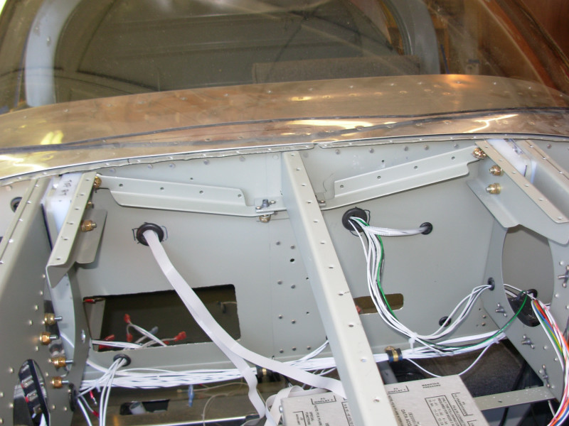
The ribbon cable passing through the sub-panel on the left is for the two IK-2000 engine monitor display boxes. The pass-through on the right side are the Dynon D-100 wires. This photo also shows the modification I made to the canopy attachment bolts/pins. The angles secured by AN-3 bolts & nutplates are holding the canopy hinge pins (eye bolts with threads ground off) in place. If I ever need to pull the canopy, I can access those two bolts from below and just pull the hinge pins out using the angles:
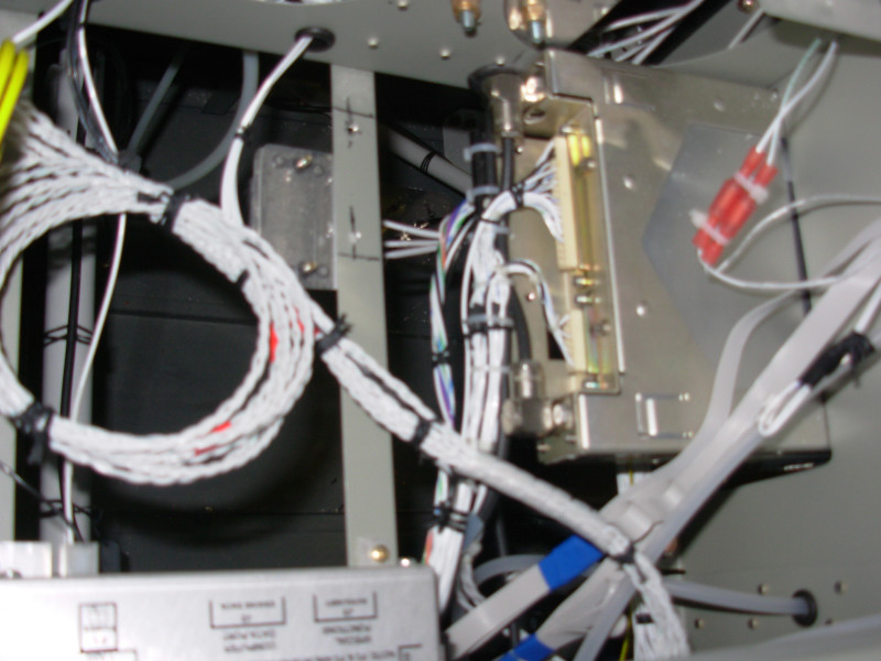
This photo shows the back side of the SL-30 nav/comm and Garmin GTX-327 transponder avionics trays. The coiled up wire harness is from the IK-2000 engine monitor "brain box" going out to the firewall-forward engine compartment:
This photo is the backside of the sub-panel on the pilot side. The large D-sub connector at the bottom is for the CDI with the wires passing through above that being part of the Dynon D-100 wiring harness. The small wire run coming from the Dynon pass through and then going back through the sub-panel are the serial port wires going to the D-sub connector I mounted just behind the GPS in the panel. That port is normally connected to the GPS or SL-30 nav (selectable by toggle switch) for driving the Dynon's DG or HSI display. The other use for that port is maintenance; you can connect a laptop to upload/update the customized checklists in the Dynon or to update the Dynon firmware:
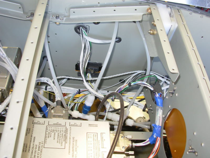
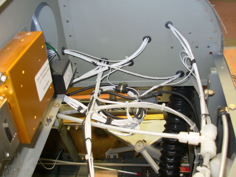
This photo shows the back of the sub-panel on the pilot's side. The gold box on the left is the Trio EZ-1 altitude hold "brain box" and MEMS sensor. The small black box just aft of the Trio box is the Dynon altitude encoder converter that takes the Dynon serial mode C altitude data and converts it to the parallel "grey" code altitude data signal. My transponder would take the serial data but my IK-2000 only reads the parallel data format so I convert it, send it through the IK-2000 and then on to the GTX-327 transponder. The static line can be seen here as well, with the T-fitting allowing a line to feed the Trio EZ-1 altitude hold sensor. The pitot line is also visible, running through the wiring runs just aft of the static lines:
Panel: pg 1 | pg 2 | pg 3 | pg 4 | pg 5 | pg 6 Electrical: pg 1 | pg 2 | pg 3 | pg 4 | pg 5 | pg 6 | pg 7 | pg 8
|
|
This page was last updated on 12/18/11.
Click here for questions or feedback. Copyright © 2007. All rights reserved. Chris Hand, chris@ckhand.com
|