|
|
|
Aviation Links:
|
Panel: pg 1 | pg 2 | pg 3 | pg 4 | pg 5 | pg 6| pg 7 Electrical: pg 1 | pg 2 | pg 3 | pg 4 | pg 5 | pg 6 | pg 7 | pg 8
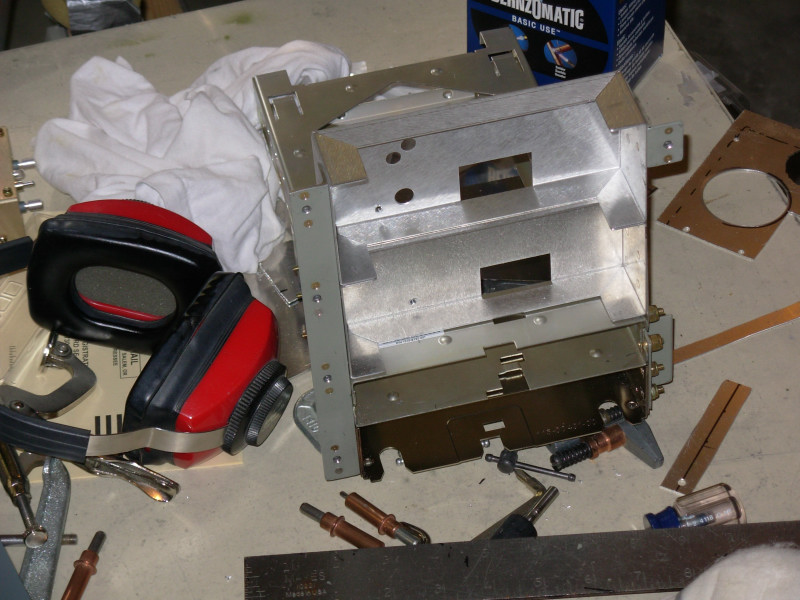
The top two trays here are for the IK-2000 engine monitor display boxes. Third down in the stack is the tray for the SL-30 NavCom and the bottom tray is for the Garmin GTX-327 transponder. I tied all the trays together with the aluminum angle on the left side and a smaller angle support on the top, right side. I couldn't fit an angle along the full right side because of interference with the right side support rib behind the panel. I suppose I could have moved the rib as others have done, but it seemed like more hassle than needed as I was able to establish adequate support at the panel and sub-panel.
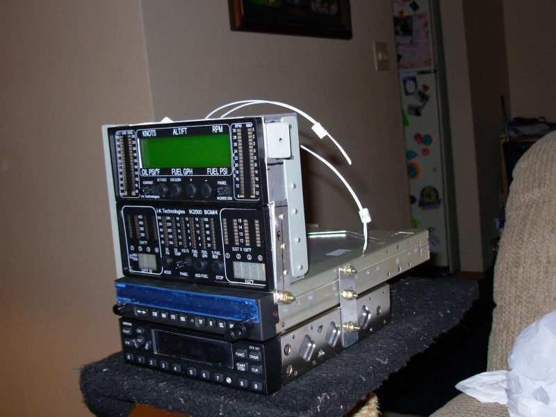
Here are the avionics and engine monitor screens installed in the trays. This angle shows how I tied the trays together with aluminum strips and then angle support that screws to the panel:
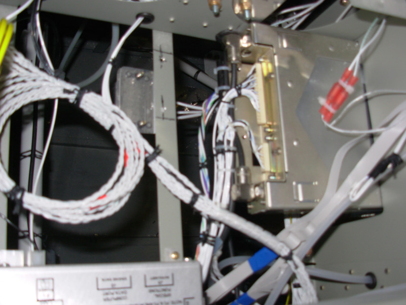
Here's a picture of the backside of the avionics tray that shows the wiring harnesses for the SL-30 NavCom and GTX-327 transponder. I did most of my own wiring, including making some of the wiring harnesses, but some avionics require that pre-made harnesses be supplied when you buy the radios. I bought my avionics from John Stark of Stark Avionics and highly recommend him - best prices I could find, great job on pre-made harnesses and although I didn't need too much in the way of customer support, my experiences were good and I've heard only good things from others that have bought from him.
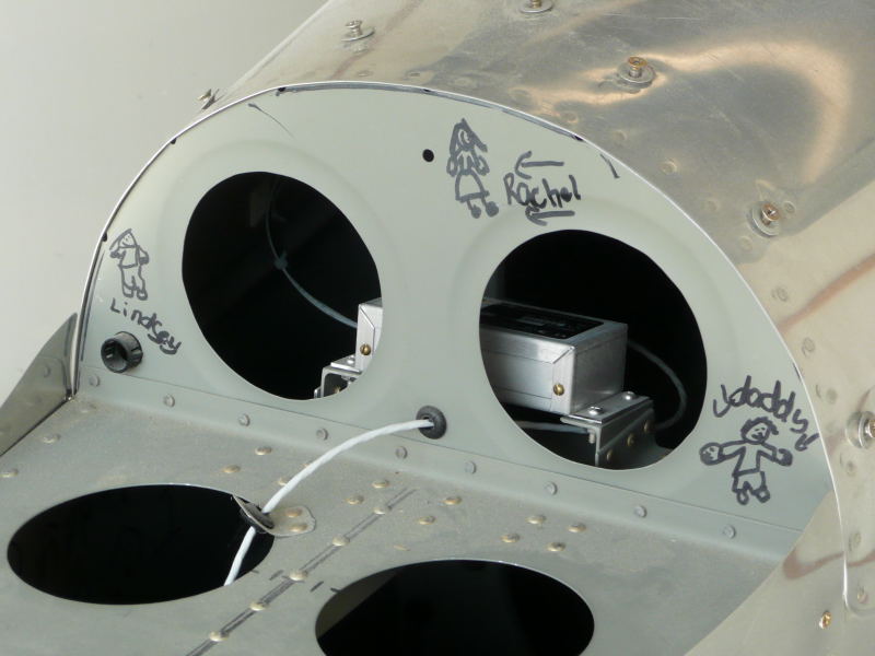
This picture is really to show where and how I mounted the Dynon D-100 remote Electronic Digital Compass (EDC) box, but you can also see some of the great artwork my youngest daughter put on my plane a few years back. When she was 5 or 6 years old she used to come out to the garage and ask if she could help me build my airplane, so I would give her a Sharpie pen and tell her I needed some decorations on the plane - the drawings here in the tail area are some of the results of that, along with a bunch of similar drawings all over the inside of the tailcone (upside down drawings since the fuselage was upside down in the jig at the time those were done). The skins were already primed and I will never touch up or paint over that artwork! The EDC mounting tray is adjustable so I can make adjustments if needed as the EDC has to be mounted within some fairly tight alignment requirements. The cable coming through the bulkhead under the EDC goes to the temperature probe for the Dynon. The temperature probe is installed under the left horizontal stabilizer where I hope it is out of sight and gives a somewhat accurate reading:
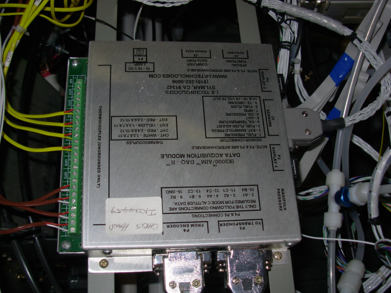
This is the "brain box" for the IK-2000 engine monitor, mounted on rails I installed behind the panel and above the rudder pedals. I tried my best to make it removable from underneath but am still worried I might have to eventually make an access panel in the forward top skin for adequate maintenance access:
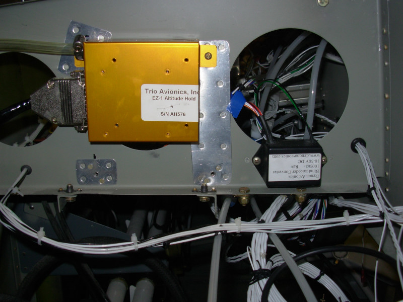
This is the sensor and "brain box" for the Trio EZ-1 altitude hold instrument. I made the wiring harness myself and you can see the static line input at the top left in this picture (top, forward as installed in the plane). The upside down black box aft of the EZ-1 box is the serial to parallel converter box I bought from Dynon to take the serial Mode C altitude encoder signal from the Dynon and convert it to standard parallel signal that runs through the IK-2000 box and to the GTX-327 transponder. The Garmin transponder can take a serial input but the IK-2000 can only read the parallel signal, so I added the converter:
Panel: pg 1 | pg 2 | pg 3 | pg 4 | pg 5 | pg 6| pg 7 Electrical: pg 1 | pg 2 | pg 3 | pg 4 | pg 5 | pg 6 | pg 7 | pg 8
|
|
This page was last updated on 12/18/11.
Click here for questions or feedback. Copyright © 2007. All rights reserved. Chris Hand, chris@ckhand.com
|