|
|
|
Aviation Links:
|
Panel: pg 1 | pg 2 | pg 3 | pg 4 | pg 5 | pg 6 Electrical: pg 1 | pg 2 | pg 3 | pg 4 | pg 5 | pg 6 | pg 7 | pg 8
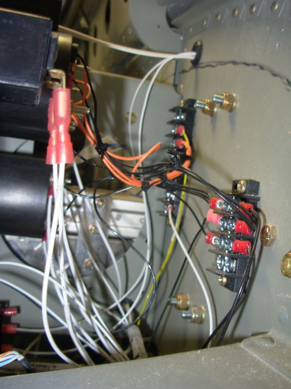
This photo shows a side view of the back of the panel from the passenger side. The two terminal strips shown are the power and ground strips respectively for some of the mechanical gauges. The power terminal strip is controlled by a voltage regulated dimmer switch to allow for dimming instrument lights.
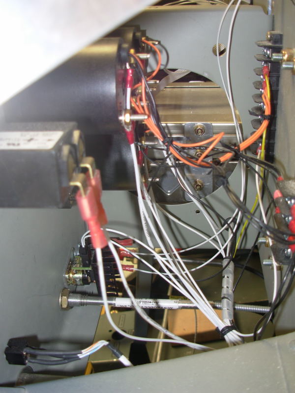
Another view of same area shown in picture above. Here you can see the Hobbs meter close on left, and the voltage regulator light dimmer switch on lower part of the panel next to the cabin heat Bowden cable:
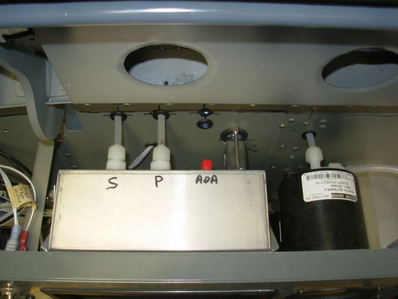
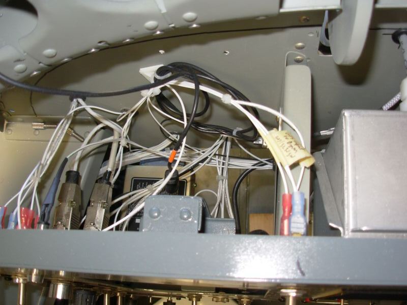
A top view of the back side of center section of the panel is shown here. The tubing is the static line going to both the mechanical style altimeter (backup) and to the IK-2000. The other tube going to the back of the IK-2000 display is the pitot line which was tee'd off from the Dynon. The IK-2000 is primarily an engine monitor, but also provides airspeed and altitude displays so functions as a backup to the Dynon:
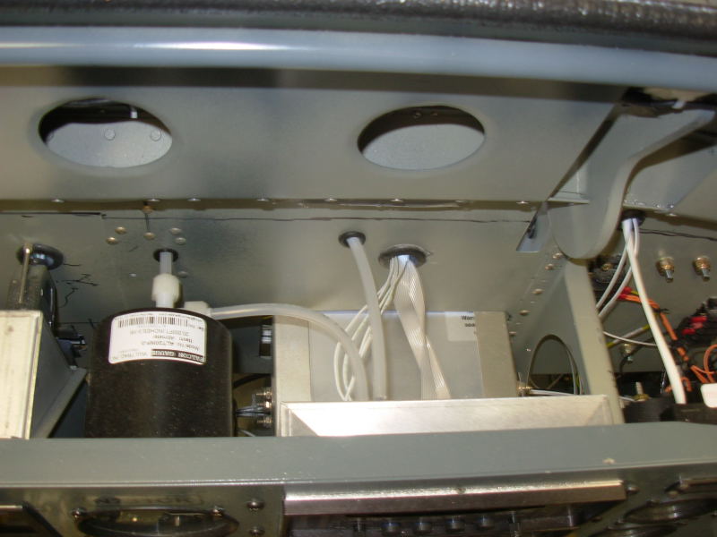
Another top view of the center section of the panel, this one showing the top/back of the Dynon D-100 box. The static and pitot lines can be seen here as well as the main wiring harness connection to the D-100. The Angle of Attack port is plugged for now, but I may upgrade to the Dynon pitot tube sometime in the future to add the AoA display to the Dynon:
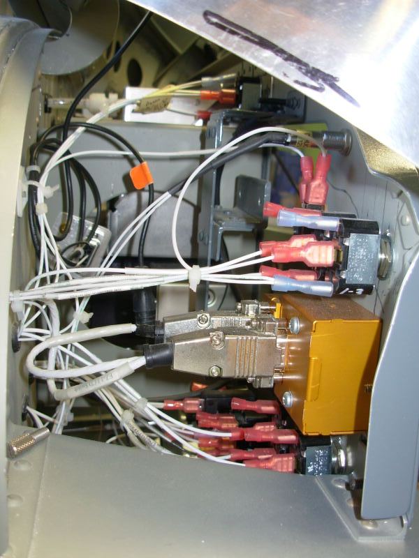
The backside of the panel on the pilot side is a bit of a wiring mess due to all the switches and controls I put there, but it works and is accessible for maintenance:
Side view of the panel backside on the pilot's side. The gold box is the control knob & button for the Trio EZ-1 altitude hold. The gray painted bracket that doesn't have anything attached in this picture is the bracket I made to panel mount my portable Lowrance 2000C GPS.
Panel: pg 1 | pg 2 | pg 3 | pg 4 | pg 5 | pg 6 Electrical: pg 1 | pg 2 | pg 3 | pg 4 | pg 5 | pg 6 | pg 7 | pg 8
|
|
This page was last updated on 12/18/11.
Click here for questions or feedback. Copyright © 2007. All rights reserved. Chris Hand, chris@ckhand.com
|