|
|
|
Aviation Links:
|
Panel: pg 1 | pg 2 | pg 3 | pg 4 | pg 5 | pg 6 Electrical: pg 1 | pg 2 | pg 3 | pg 4 | pg 5 | pg 6 | pg 7 | pg 8
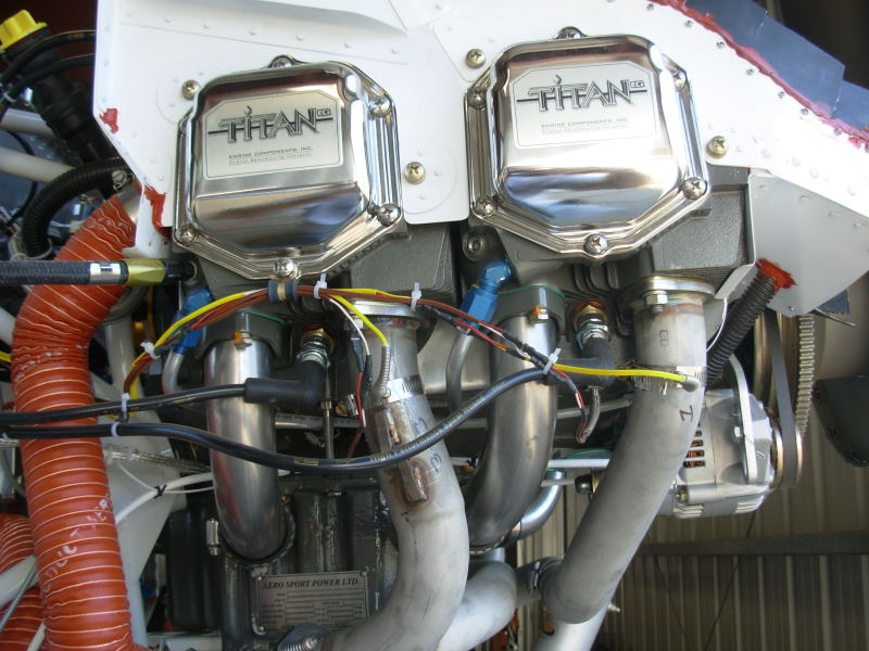
On the right side of the engine I routed the EGT and CHT probe wires outside the intake and exhaust pipes, clamping them to the cylinder cover:
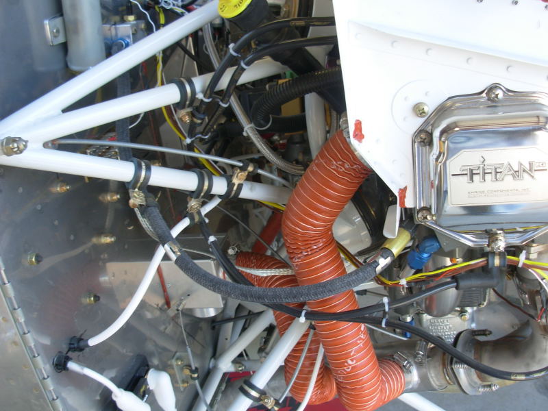
The EGT and CHT probe wires continue up to the top center of the firewall where all four cylinders worth penetrate the firewall and connect to the engine monitor "brain box":
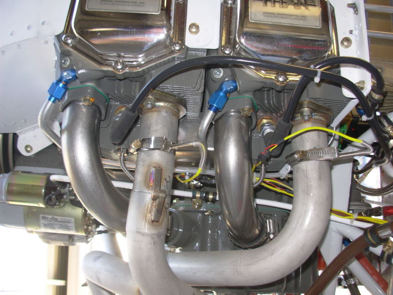
On the left side of the engine I routed the EGT and CHT probe wires inside the intake pipes, clamping them to the baffles tie wire and then the engine mount tubes before routing up to the firewall:
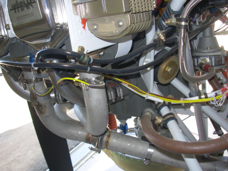
Here's a shot of the left side probe wires coming out of the engine underside area, clamped to the big starter wire:
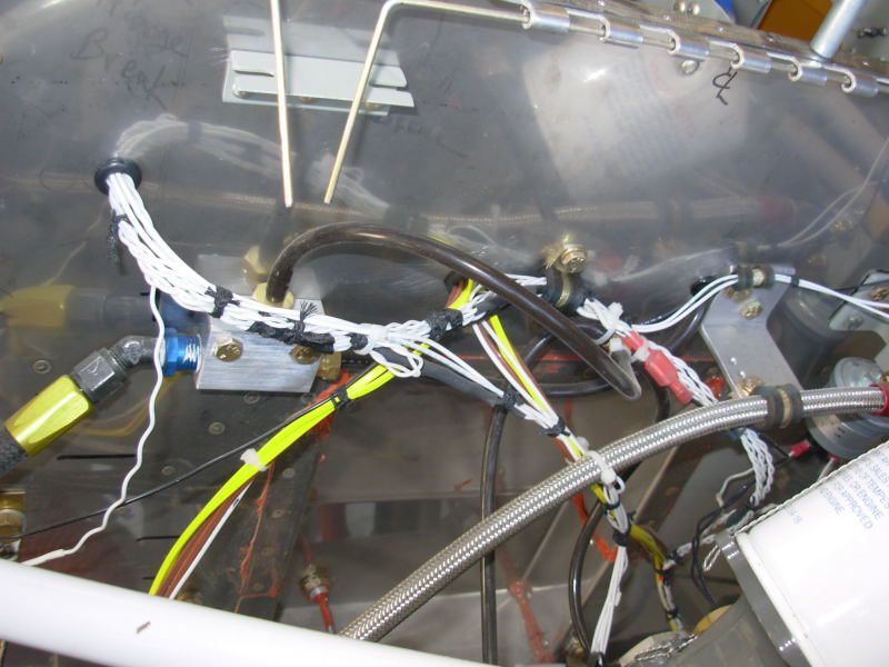
This shows where the EGT and CHT probe wires pass through the firewall to the engine monitor "brain box". Other firewall forward wiring can also be seen here as well as the manifold pressure sense lines that are tee'd off to the P-Mags and to the engine monitor (penetrations will be sealed with high temp RTV before first engine run and might add SS heat shields as well):
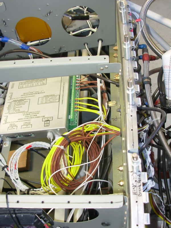
On the cockpit side of the firewall, this shows the connections to the IK-2000 engine monitor box. I wasn't sure if shortening the probe wires would affect the accuracy so I just coiled them here. The extra length gives flexibility for changes later and I mounted the engine monitor box on rails that can be removed from below since after the top skin is riveted it would be near impossible to get at the EGT/CHT sensor wire connections without lowering the engine monitor box to where I can get at it. I might also cut an access panel in the top skin at some point but want to avoid it if possible.
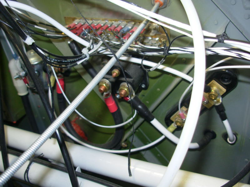
Also on the cockpit side of the firewall, on the lower part of the passenger side, I've got the common ground block, the battery and starter contactors, and the ammeter shunt:
Panel: pg 1 | pg 2 | pg 3 | pg 4 | pg 5 | pg 6 Electrical: pg 1 | pg 2 | pg 3 | pg 4 | pg 5 | pg 6 | pg 7 | pg 8
|
|
This page was last updated on 12/18/11.
Click here for questions or feedback. Copyright © 2007. All rights reserved. Chris Hand, chris@ckhand.com
|