|
|
|
Aviation Links:
|
Panel: pg 1 | pg 2 | pg 3 | pg 4 | pg 5 | pg 6 Electrical: pg 1 | pg 2 | pg 3 | pg 4 | pg 5 | pg 6 | pg 7 | pg 8
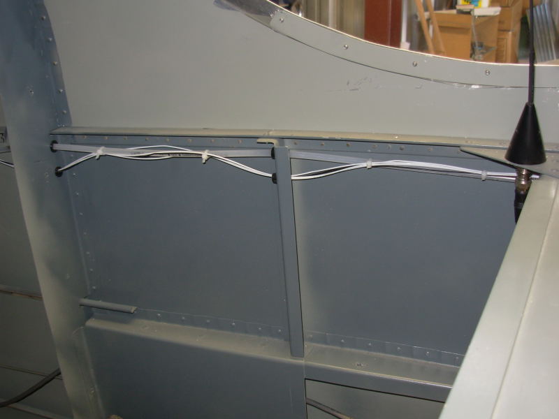
Rather than drilling additional pass through holes in the main wing spar, most of my wiring that had to go aft of the spar was routed along the main fuselage longerons. I put one of the Bob Archer wingtip nav antenaes in the right wingtip and this photo shows the nav antenae coax cable that is routed down through the seat pan and out to the wing. The white wires along the coax were for the passenger side push to talk (PTT) switch but I later pulled those out to put the passenger side PTT switch in the panel. I decided it would be easier to install/remove the passenger stick if I didn't have to mess with the PTT wires. I expect relatively frequent passenger side stick install/removal as my wife will never want the stick installed and my son will always want the stick installed. The other wires seen in this photo continue back to behind the baggage compartment bulkhead for the strobe light power supply and Trio EZ-1 altitude hold servo. This is one of the "in progress" pictures; the wiring under the seat pan was cleaned up and tied off before close out:
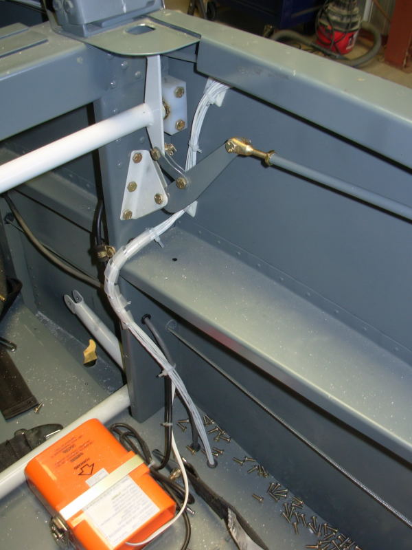
This photo shows the wiring bundle that passes from forward of the panel, under the pilot side rail and under the seat pan floor out to the wings. The wires in this bundle include power for nav lights on both wings, Trio EZ-Pilot wiring for the wing leveler servo mounted in the left wingtip area and ELT connection to panel control box. The ELT is shown here and is mounted in the space behind the pilot seat, forward of the flap actuating bar:
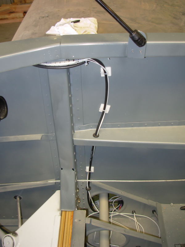
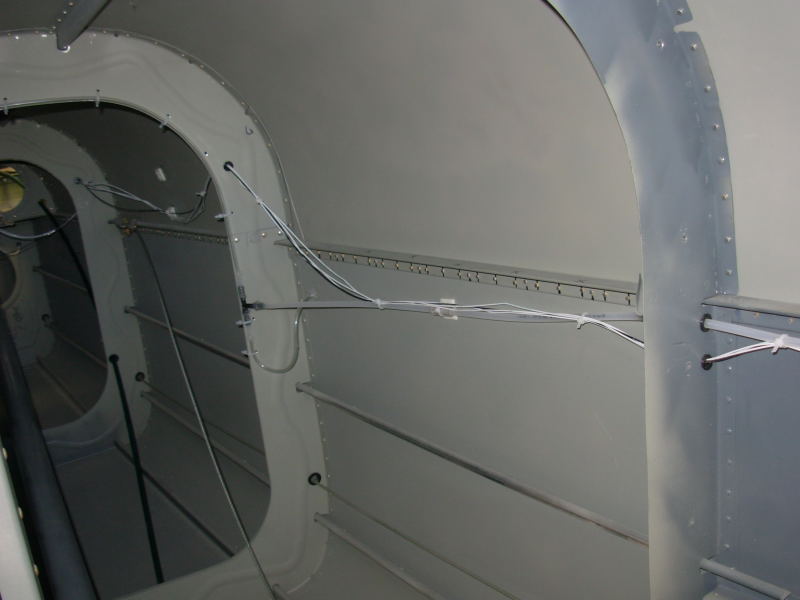
A closer look at the wiring bundle from forward along with the ELT antenae cable (mounted along the roll bar). The gray shielded cable above the rudder cable is the left wingtip strobe light cable coming from the strobe light power supply that is mounted aft of the baggage compartment bulkhead:
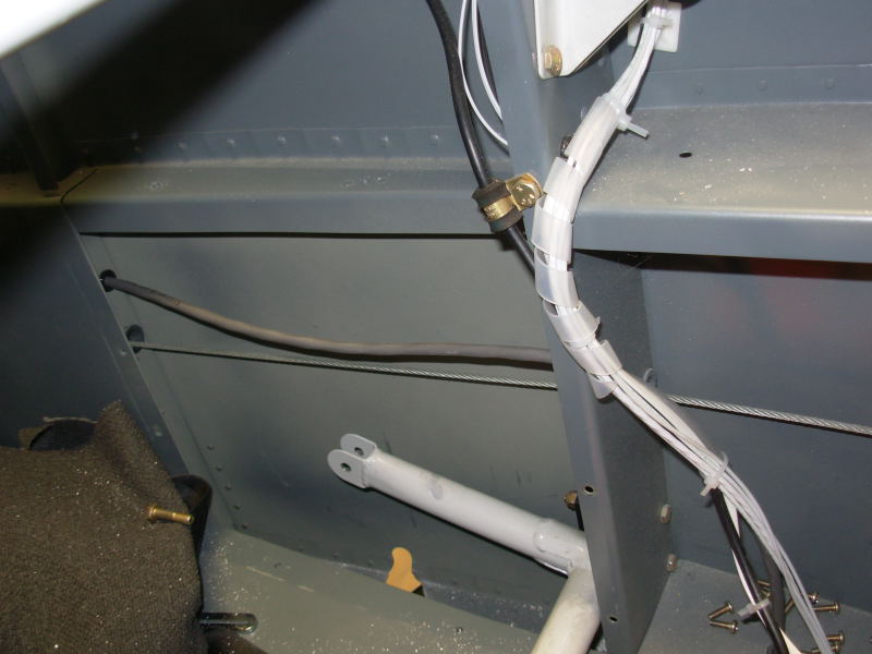
This photo of the pilot side baggage compartment area shows the routing for the static port tubing and the routing of the wires for the Dynon Electronic Digital Compass (EDC) that is mounted in the tail area to provide compass and outside air temp data to the Dynon EFIS in the panel (the OAT probe is mounted under the horizontal stabilizer and is connected to the EDC). You can also see the ELT antenae mounted here, just aft of the roll bar:
Dynon EDC wiring and static system tubing continues aft towards the tail and the static ports:
Panel: pg 1 | pg 2 | pg 3 | pg 4 | pg 5 | pg 6 Electrical: pg 1 | pg 2 | pg 3 | pg 4 | pg 5 | pg 6 | pg 7 | pg 8
|
|
This page was last updated on 12/18/11.
Click here for questions or feedback. Copyright © 2007. All rights reserved. Chris Hand, chris@ckhand.com
|