|
|
|
Aviation Links:
|
Panel: pg 1 | pg 2 | pg 3 | pg 4 | pg 5 | pg 6 Electrical: pg 1 | pg 2 | pg 3 | pg 4 | pg 5 | pg 6 | pg 7 | pg 8
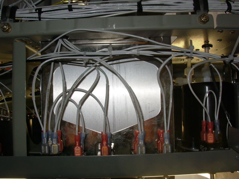
This page shows the wiring runs from underneath the panel. This first shot is from under the right, center section of the panel, underneath the radio stack. The switches shown here are the controls for lighting systems (nav, landing, taxi, and wig/wag controls for the landing/taxi lights). The main cable run from the buss area on right side of plane across to left side of the plane can be seen just forward of the sub-panel:
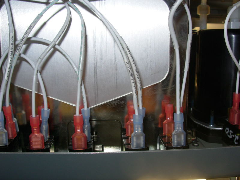
Here's a closer up shot of the light switches where you can see the wire label method I used (small print from home computer placed inside clear shrink wrap on the wire):
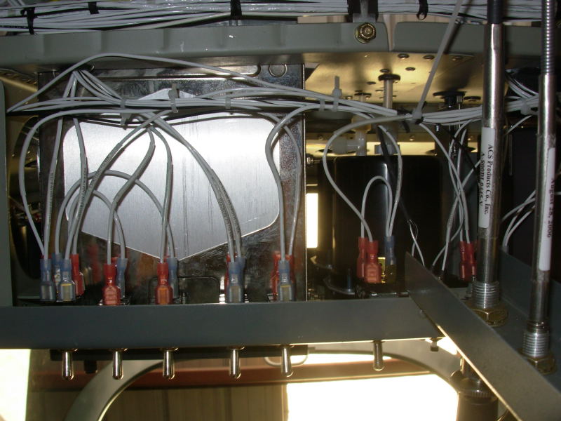
Wider angle shot of same area with center console visible:
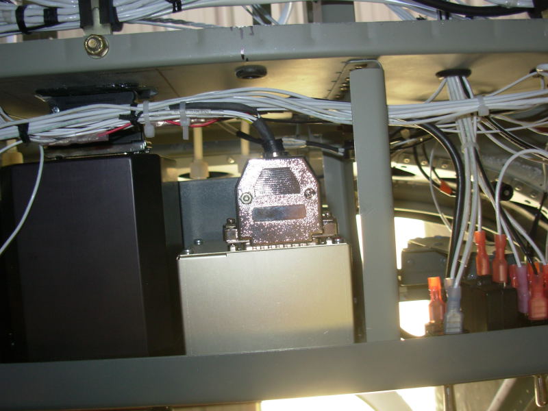
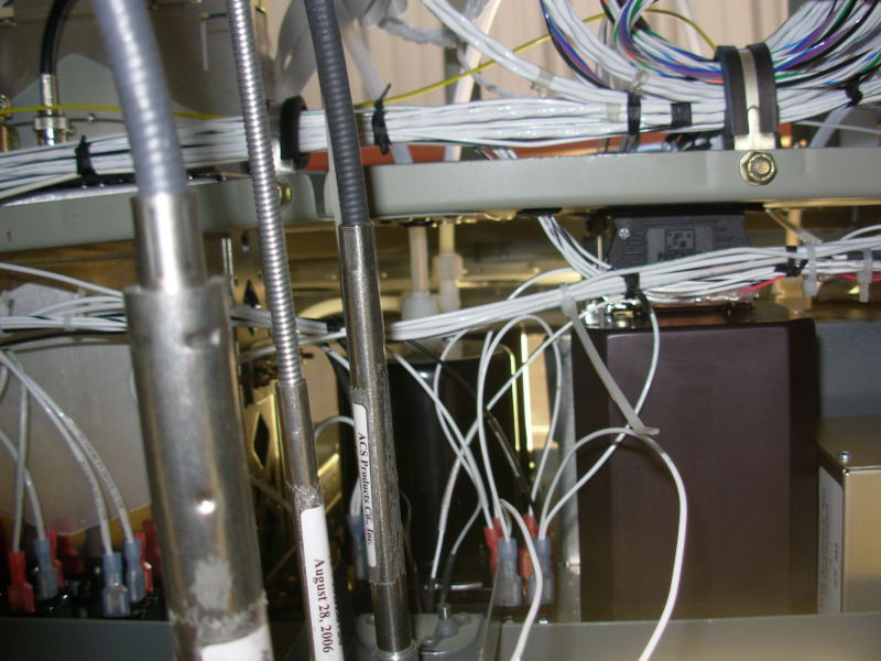
This is the underside view of the pilot side of the panel. The bottom light colored box is the Trio EZ-Pilot wing leveler control box (I made that harness myself, only the transponder, nav/comm, intercom and CDI harnesses came pre-made). The bottom black box is the Mid-Continent CDI with pre-wired harness connecting through the back of the sub-panel:
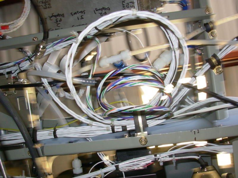
Underside view of the center of the panel; the flap control wires are not cleaned up yet in this shot (the wires dangling down near the center console). The coiled wires in upper right part of the photo is the extra length of the intercom pre-wired harness as I was a bit too conservative in estimating required length when I ordered the avionics:
A further aft shot of same general area of underside of the panel. These coiled wires are the extra length of pre-made intercom harness. The static and pitot lines can be seen here as well:
Panel: pg 1 | pg 2 | pg 3 | pg 4 | pg 5 | pg 6 Electrical: pg 1 | pg 2 | pg 3 | pg 4 | pg 5 | pg 6 | pg 7 | pg 8
|
|
This page was last updated on 12/18/11.
Click here for questions or feedback. Copyright © 2007. All rights reserved. Chris Hand, chris@ckhand.com
|